Extrasensory II
Specifics of the rebuild are presented in excruciating detail below. |
||||
Since there was no other entries in the Lightweight Autonomous Sumo class, Extrasensory competed in the Heavyweight Autonomous Sumo class 2005 NEIRG. Although it did not come close to winning, Extrasensory did well against some sumos that were three times it weight.
Videos of the 2005 NEIRG Competition:
|
||||
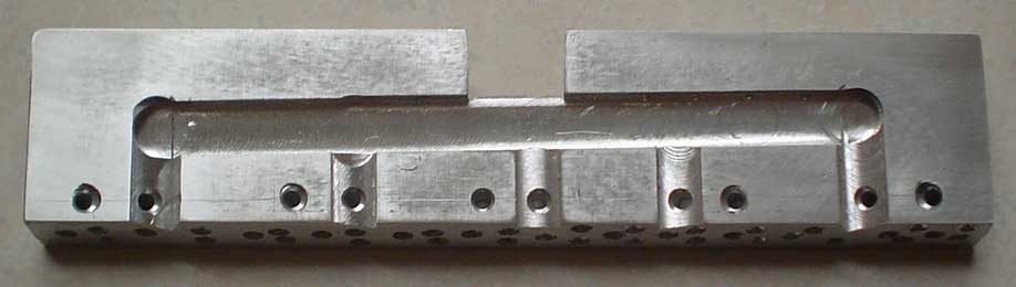 The rebuild started with new sensors in the front bumper. This is the back side of the aluminum bumper with machined mountings for the electronics. Having machined recesses for the IR LEDs and PNA4602 sensors assures proper alignment. Due to the low mounting, the sensors are all angled up 20 degrees from horizontal and are angled out 15 degrees and 30 degrees. An experienced machinist might not be awed by quality of the piece, but two grown males who think that they know everything, using a milling machine for the first time, was really quite amusing. Luckily, the first piece was usable. The rebuild started with new sensors in the front bumper. This is the back side of the aluminum bumper with machined mountings for the electronics. Having machined recesses for the IR LEDs and PNA4602 sensors assures proper alignment. Due to the low mounting, the sensors are all angled up 20 degrees from horizontal and are angled out 15 degrees and 30 degrees. An experienced machinist might not be awed by quality of the piece, but two grown males who think that they know everything, using a milling machine for the first time, was really quite amusing. Luckily, the first piece was usable.
|
||||
 The five Panasonic PNA4602 sensors were glued into their recesses with black RTV. The small diodes were already attached. I've since found out that the diodes are not needed. The open collector of the PNA4602 allows all of the outputs to be tied together without extra components. The five Panasonic PNA4602 sensors were glued into their recesses with black RTV. The small diodes were already attached. I've since found out that the diodes are not needed. The open collector of the PNA4602 allows all of the outputs to be tied together without extra components. |
||||
 The +5 Volt and ground leads were wired to the sensors. A small capacitor was added for a little power filtering. The +5 Volt and ground leads were wired to the sensors. A small capacitor was added for a little power filtering. |
||||
 A little heat shrink tubing was added to isolate the diodes and the sensor leads were wired together. Refer to the page on Excuse II for a schematic of the circuit. A little heat shrink tubing was added to isolate the diodes and the sensor leads were wired together. Refer to the page on Excuse II for a schematic of the circuit. |
||||
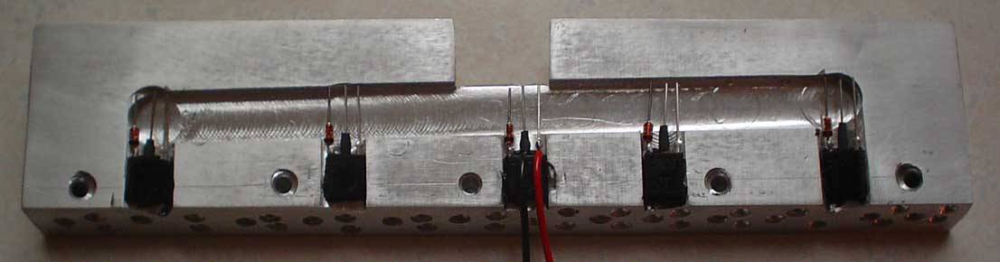
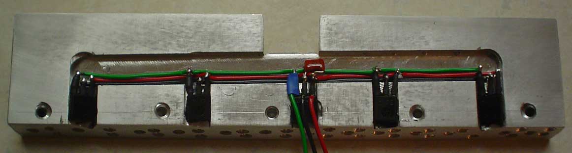
 A 10.0 K ohm 0805 size resistor was soldered between the gate and source leads of each IRFD024 FET. A wire was attached to the gate lead and the FETs were glued onto the bumper. The QEC113 IR LEDs were glued in and care was taken to properly align their leads. A 10.0 K ohm 0805 size resistor was soldered between the gate and source leads of each IRFD024 FET. A wire was attached to the gate lead and the FETs were glued onto the bumper. The QEC113 IR LEDs were glued in and care was taken to properly align their leads. |
||||
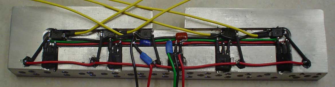 The IR LED wiring was added along with the power and ground wires for the FETs. The blue 10 mf tantalum can be seen, but the 33 ohm resistor is covered with heat shrink. Note that the power and ground for the FETs is completely separate from the PANA4602 power and ground. The wiring is now completed. The IR LED wiring was added along with the power and ground wires for the FETs. The blue 10 mf tantalum can be seen, but the 33 ohm resistor is covered with heat shrink. Note that the power and ground for the FETs is completely separate from the PANA4602 power and ground. The wiring is now completed. |
||||
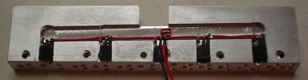
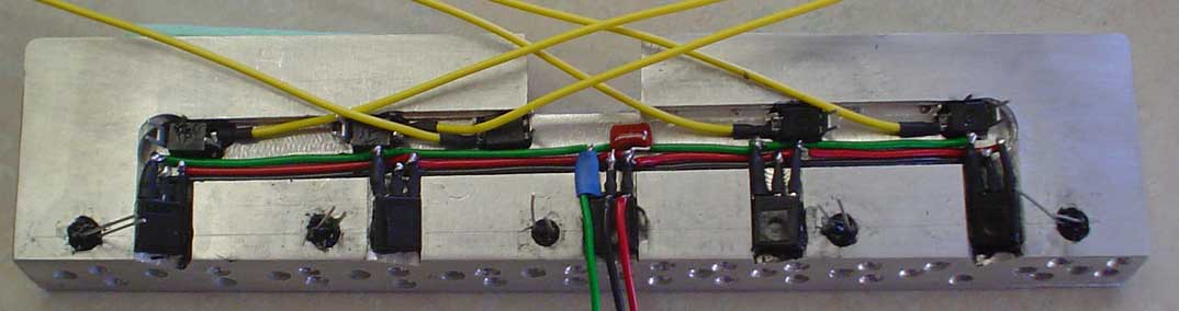
 The wires were neatly arranged and the sensor array was tested. It is difficult to see in the photo, but small pieces of black plastic electrical tape were added to the rear surface of the PNA4602 sensors. IR radiation can enter the rear of the sensors and give false readings. At this stage there is no optical crosstalk, but normally a little electrical crosstalk between the test wires (about 20 inches long). Once the bumper is mounted in the robot, the wires are under 6 inches long and crosstalk is not a problem. The wires were neatly arranged and the sensor array was tested. It is difficult to see in the photo, but small pieces of black plastic electrical tape were added to the rear surface of the PNA4602 sensors. IR radiation can enter the rear of the sensors and give false readings. At this stage there is no optical crosstalk, but normally a little electrical crosstalk between the test wires (about 20 inches long). Once the bumper is mounted in the robot, the wires are under 6 inches long and crosstalk is not a problem. |
||||
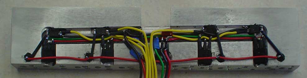
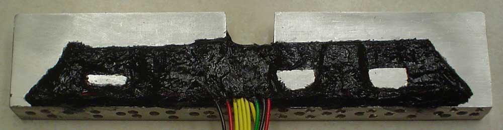 The electrical components are all sealed in black RTV. The RTV not only physically protects the wiring, it also provides electrical insulation and eliminates IR crosstalk. The electrical components are all sealed in black RTV. The RTV not only physically protects the wiring, it also provides electrical insulation and eliminates IR crosstalk.
|
||||
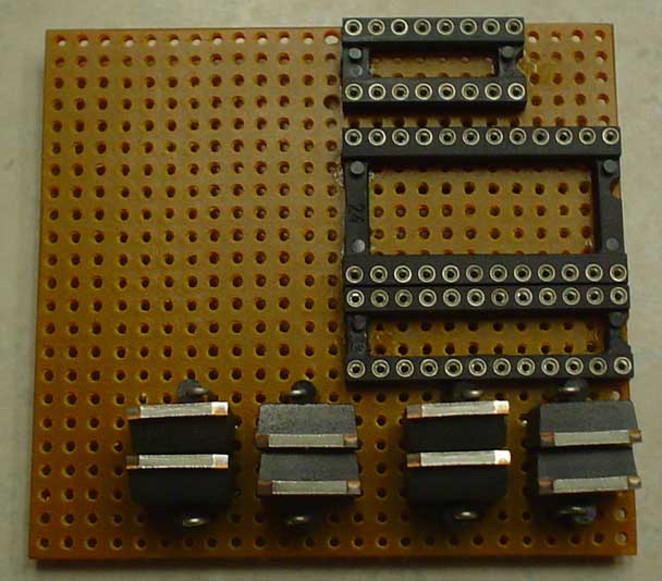
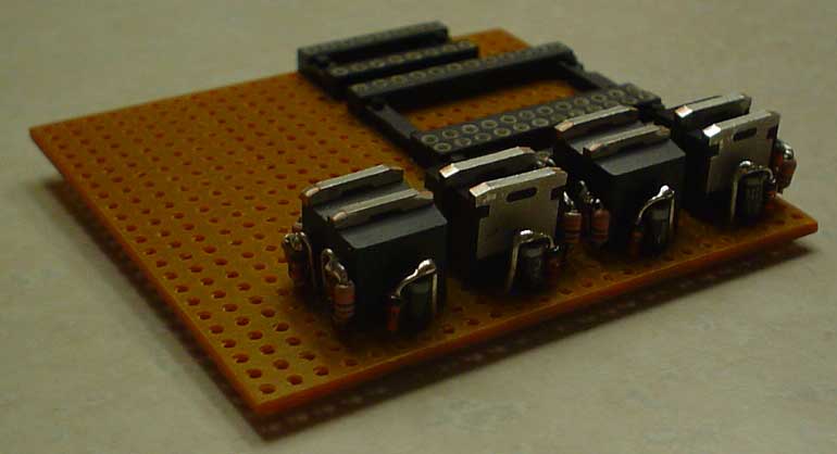
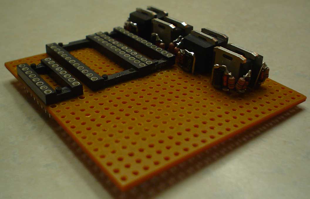
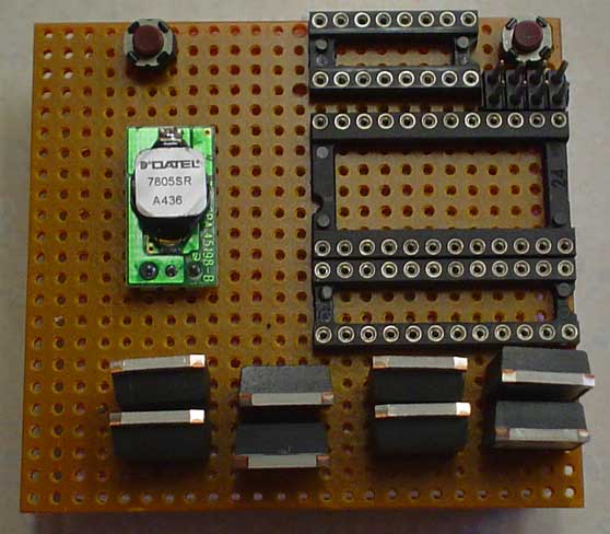 A new circuit board was produced to fit the tight packaging of Extrasensory. This photo shows the layout of the FETs, IC sockets, voltage regulator, and push buttons. The holes in the perforated board had to be enlarged to fit the FETs and the sockets. The board was cut to final size and the edges were finished with a file. The top socket is for the PAK IV, the middle socket is for the BS2SX, and the bottom socket is for the two Pololu Dual Serial Motor Controller ICs. The IC sockets are held in with super glue. A new circuit board was produced to fit the tight packaging of Extrasensory. This photo shows the layout of the FETs, IC sockets, voltage regulator, and push buttons. The holes in the perforated board had to be enlarged to fit the FETs and the sockets. The board was cut to final size and the edges were finished with a file. The top socket is for the PAK IV, the middle socket is for the BS2SX, and the bottom socket is for the two Pololu Dual Serial Motor Controller ICs. The IC sockets are held in with super glue. |
||||
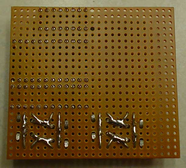
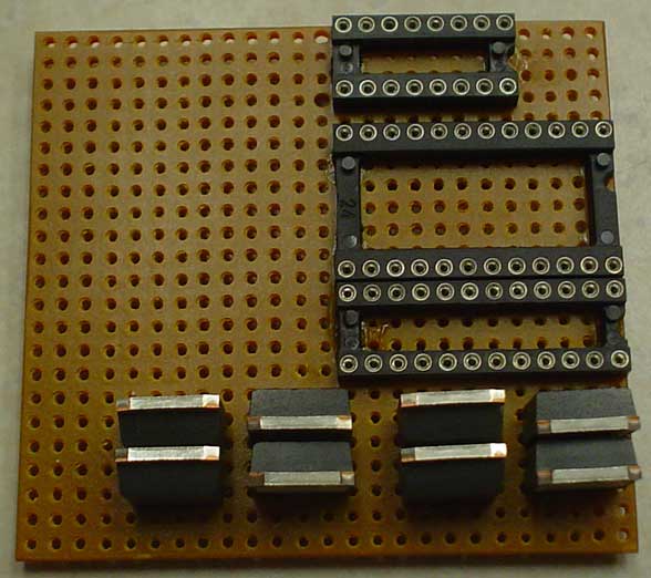  The FETs used here are the IRF4905L and the IRF3205ZL. In this application, the FETs can handle about 10 amps continuous and the motors are rated at less than 5 amps stall current. The TO262 package allowed a little lower overall height for the finished robot. The FETs used here are the IRF4905L and the IRF3205ZL. In this application, the FETs can handle about 10 amps continuous and the motors are rated at less than 5 amps stall current. The TO262 package allowed a little lower overall height for the finished robot. |
||||
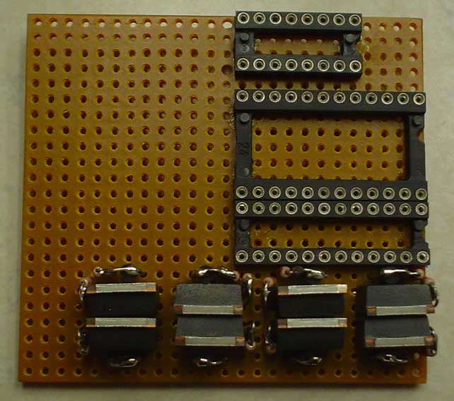
  The SR106 diodes are 1 amp rated Schottky type. Schottky diodes are preferable in this application due to their low forward voltage drop and fast turn response time. The SR106 diodes are 1 amp rated Schottky type. Schottky diodes are preferable in this application due to their low forward voltage drop and fast turn response time.
|
||||
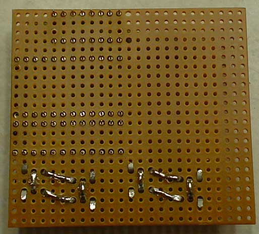
 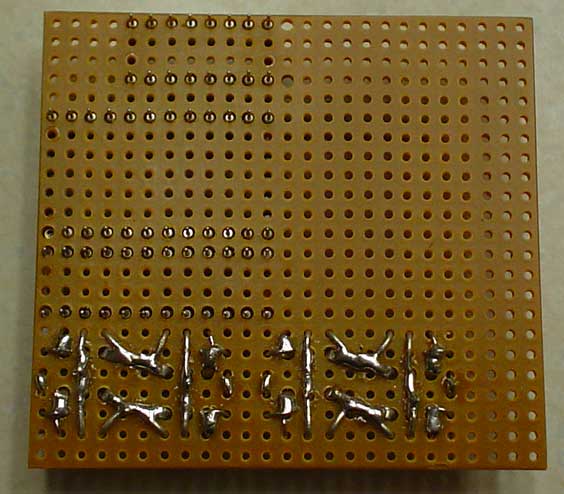 The diodes, zeners, and resistors are added that allow battery voltages greater than 20 volts, but keep the FET gate to source voltage less that 15 volts. Any gate to source voltage close to 20 volts will destroy the FETs. I learned that the hard way. The diodes, zeners, and resistors are added that allow battery voltages greater than 20 volts, but keep the FET gate to source voltage less that 15 volts. Any gate to source voltage close to 20 volts will destroy the FETs. I learned that the hard way. |
||||
  Here are two side views showing the diode, zener, and resistor mounts. It gets a bit tight, so additional photos are helpful. See the page on Excuse II for the schematic of this circuit. Here are two side views showing the diode, zener, and resistor mounts. It gets a bit tight, so additional photos are helpful. See the page on Excuse II for the schematic of this circuit. |
||||
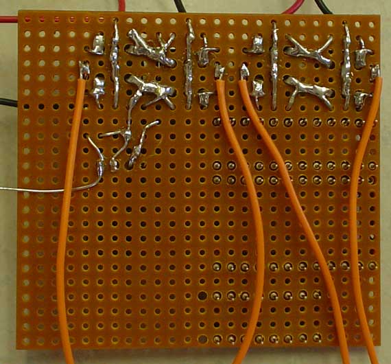
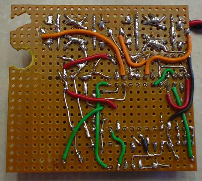
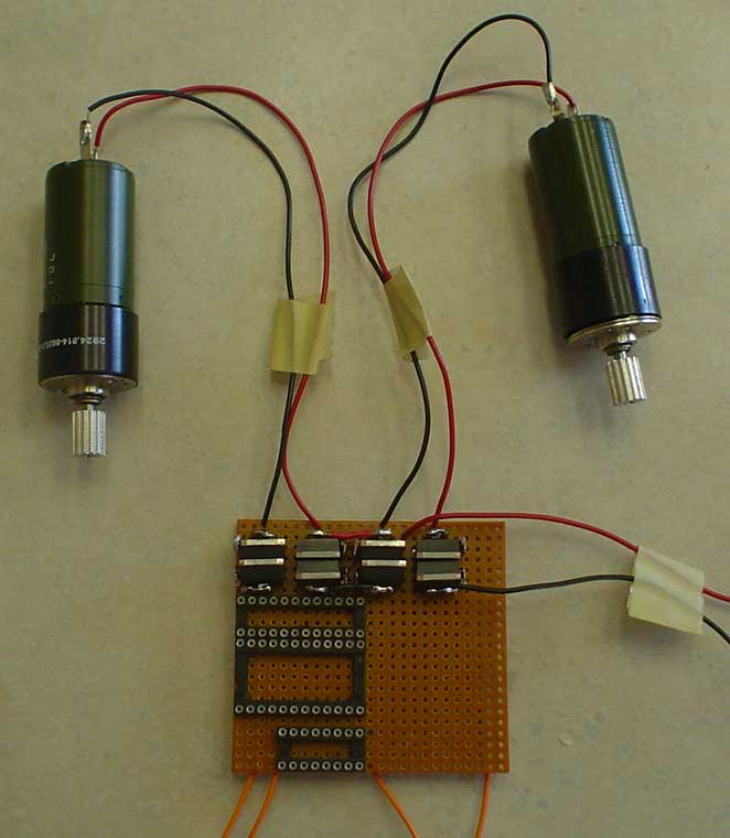 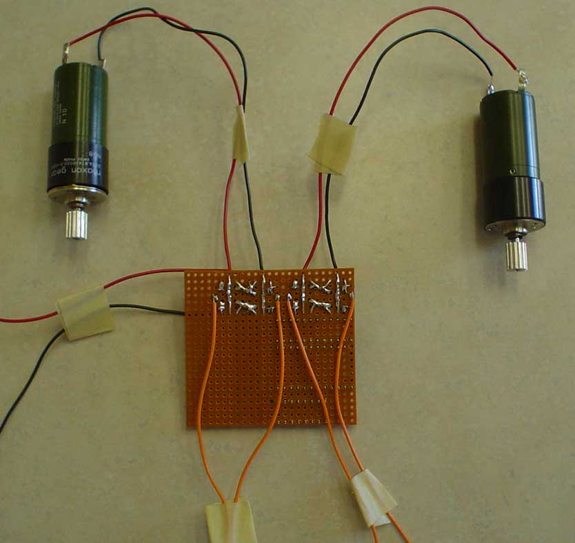 The H bridges were tested with spare motors. The orange wires are attached to the gate circuits. Short any orange wire to positive battery voltage and that motor will run. I like to check each subassembly of the circuit because wiring errors get harder to find and correct later in the build process. The H bridges were tested with spare motors. The orange wires are attached to the gate circuits. Short any orange wire to positive battery voltage and that motor will run. I like to check each subassembly of the circuit because wiring errors get harder to find and correct later in the build process. |
||||
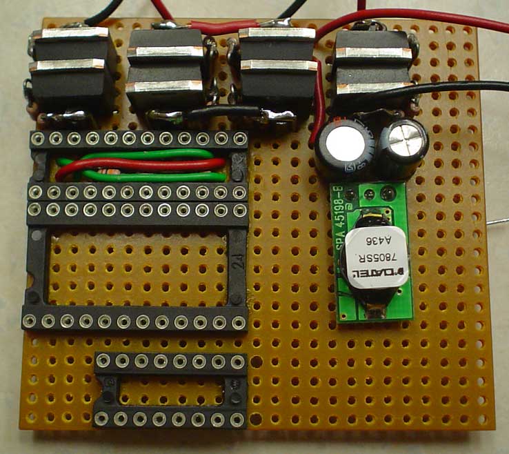
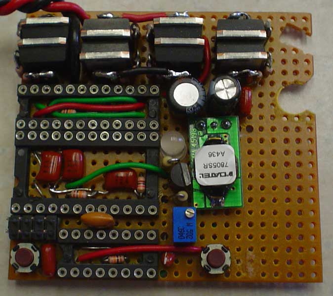
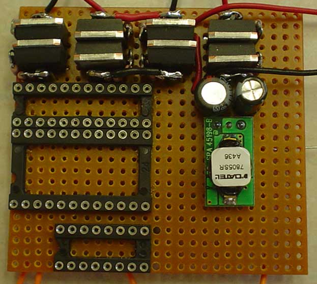  Next, the Datel 7805SR voltage regulator was added along with the filter capacitors. Again the circuit was tested for proper operation. Next, the Datel 7805SR voltage regulator was added along with the filter capacitors. Again the circuit was tested for proper operation. |
||||
 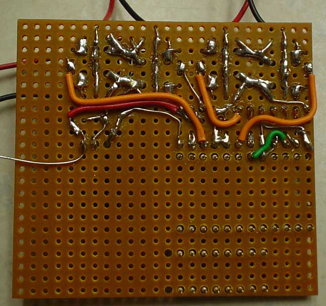 The Pololu Dual Serial Motor Controller is wired next. 10K pull down resistors were added to the SN754410 inputs as well as to the PIC12C508JN reset line. If the PIC is held in reset for any length of time, the SN754410 input voltages tend to float up, turning on both sides of the FET H bridges. This has lead to release of the magic FET smoke in the past. Again, see Excuse II for the schematic. The Pololu Dual Serial Motor Controller is wired next. 10K pull down resistors were added to the SN754410 inputs as well as to the PIC12C508JN reset line. If the PIC is held in reset for any length of time, the SN754410 input voltages tend to float up, turning on both sides of the FET H bridges. This has lead to release of the magic FET smoke in the past. Again, see Excuse II for the schematic. |
||||
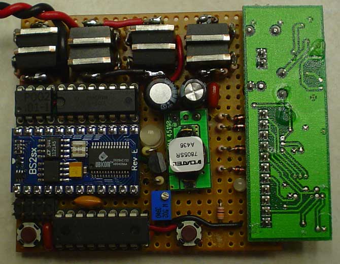
  The BS2SX, PAK IV, and the adjustable voltage regulator (for the IR LED drive current) were wired. No, no one took a bite out of the board. When mounting of the remote kill switch receiver was attempted, it was discovered that two components required cut-outs in the perforated board. Again, the operation of all of the circuits was tested. The BS2SX, PAK IV, and the adjustable voltage regulator (for the IR LED drive current) were wired. No, no one took a bite out of the board. When mounting of the remote kill switch receiver was attempted, it was discovered that two components required cut-outs in the perforated board. Again, the operation of all of the circuits was tested. |
||||
 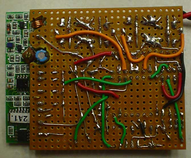 The final wiring...the kill switch receiver. See the page on Flaming P'nut for the specifics. Slowly, we start to see the rat's nest emerge from the perforated board. The final wiring...the kill switch receiver. See the page on Flaming P'nut for the specifics. Slowly, we start to see the rat's nest emerge from the perforated board. |
||||
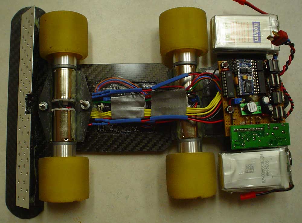 The chassis was assembled and the mouse, bumper, and motor wires were connected to the circuit board. In this photo, you can see the front bumper and optical mouse attached to one piece of carbon fiber graphite. The front motors are epoxied to small pieces of carbon fiber graphite and pivot on two bolts. The rear motors are actually mounted on a separate chassis. The motors are B62 gear motors from Robot Marketplace. The 1.75" OD tires are molded urethane similar to those used on Sticky and Excuse. The chassis was assembled and the mouse, bumper, and motor wires were connected to the circuit board. In this photo, you can see the front bumper and optical mouse attached to one piece of carbon fiber graphite. The front motors are epoxied to small pieces of carbon fiber graphite and pivot on two bolts. The rear motors are actually mounted on a separate chassis. The motors are B62 gear motors from Robot Marketplace. The 1.75" OD tires are molded urethane similar to those used on Sticky and Excuse. |
||||
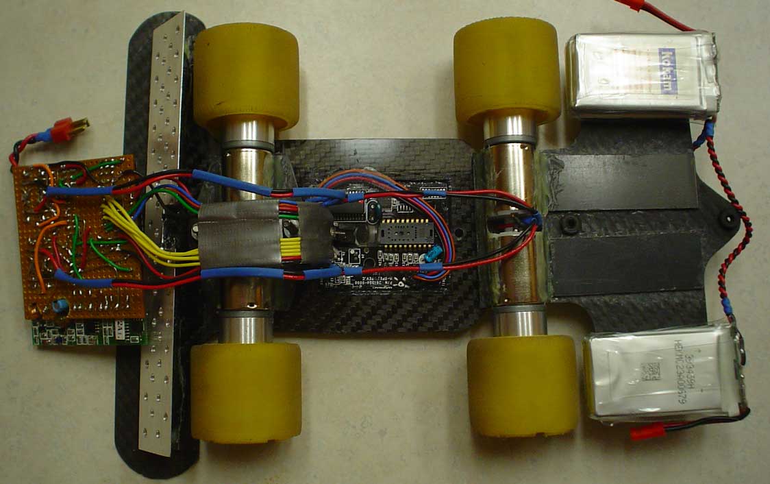 The wiring is folded over to start the final assembly. In this photo, the rear motors and batteries can be seen mounted to their own carbon fiber graphite chassis piece. The original piece of graphite was a little too flexible, so reinforcement pieces were epoxied on to add stiffness. The batteries are two 720mAh 11.1V 3-Cell Lithium-Polymer Packs from Great Planes. The wiring is folded over to start the final assembly. In this photo, the rear motors and batteries can be seen mounted to their own carbon fiber graphite chassis piece. The original piece of graphite was a little too flexible, so reinforcement pieces were epoxied on to add stiffness. The batteries are two 720mAh 11.1V 3-Cell Lithium-Polymer Packs from Great Planes. |
||||
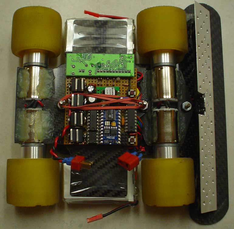
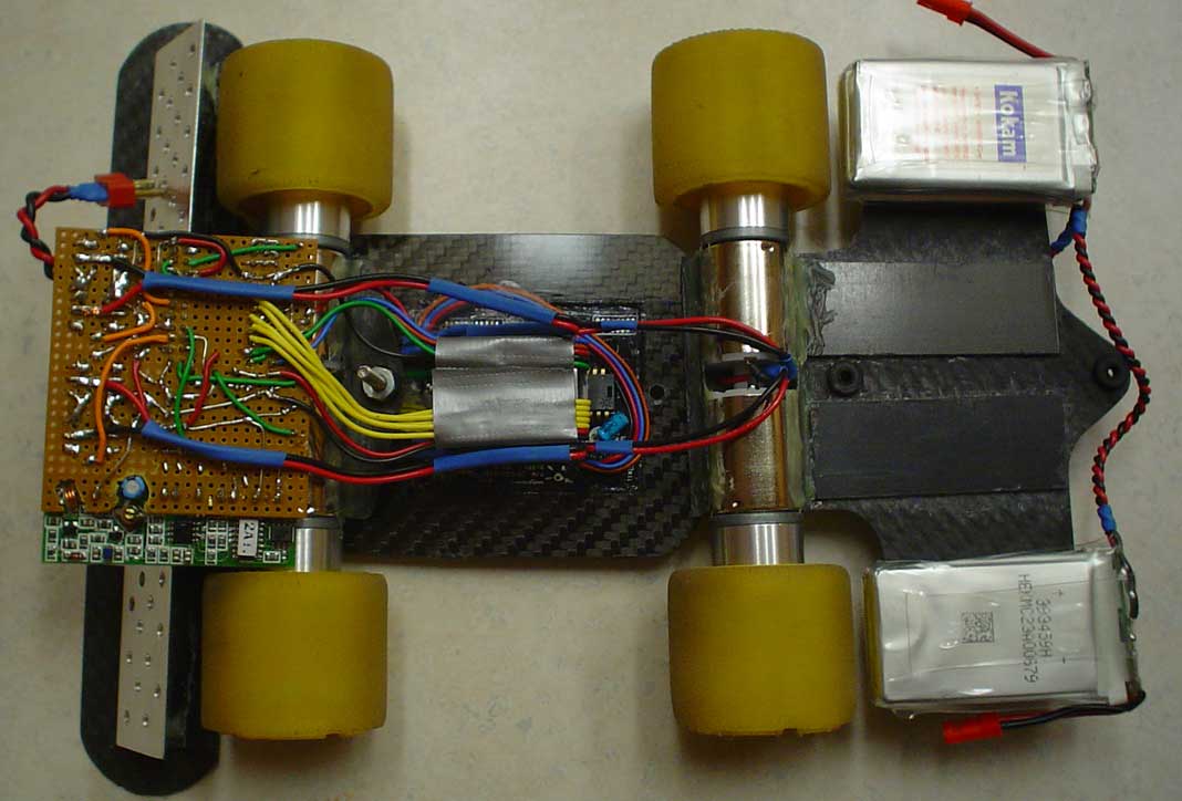 The wiring was arranged to allow access to the mounting bolts. The front mounting bolt can be seen between the mouse and the front motors. The yellow wires run on one side of the bolt and the blue and green wires run on the other side. The rear bolt isn't yet installed. The hole for the bolt can be seen just behind the mouse. Also note the two mounting grommets on the rear carbon fiber graphite chassis. The wiring was arranged to allow access to the mounting bolts. The front mounting bolt can be seen between the mouse and the front motors. The yellow wires run on one side of the bolt and the blue and green wires run on the other side. The rear bolt isn't yet installed. The hole for the bolt can be seen just behind the mouse. Also note the two mounting grommets on the rear carbon fiber graphite chassis.
|
||||
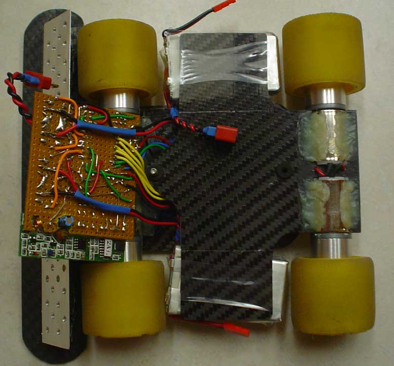 The rear chassis is now placed on the mounting bolts. The rear bolt is still not installed. I can't remember why it wasn't. Since carbon fiber graphite is conductive, clear packing tape was placed on the top of the rear chassis (not yet installed in this photo). We don't want any shorts under the circuit board. That would not be fun. The rear chassis is now placed on the mounting bolts. The rear bolt is still not installed. I can't remember why it wasn't. Since carbon fiber graphite is conductive, clear packing tape was placed on the top of the rear chassis (not yet installed in this photo). We don't want any shorts under the circuit board. That would not be fun. |
||||
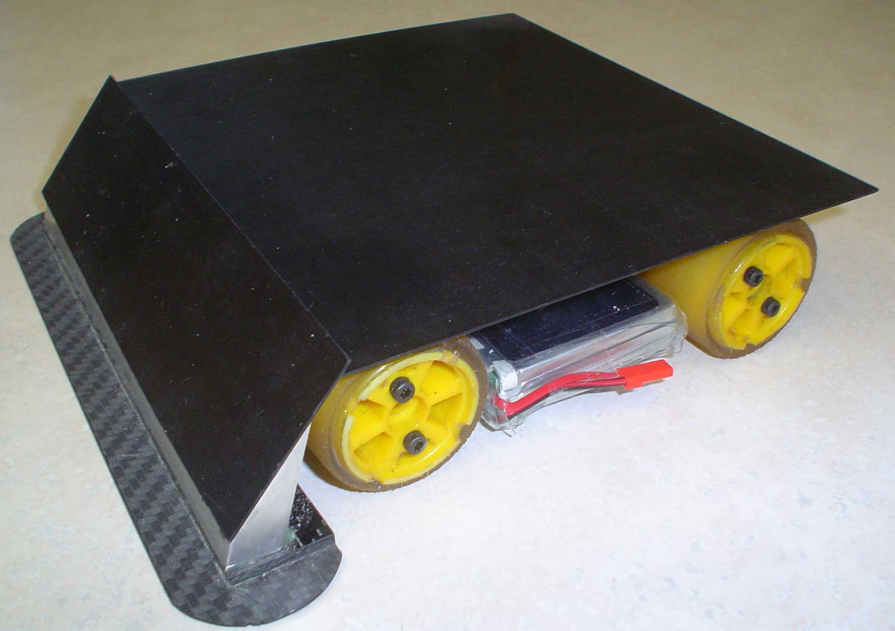
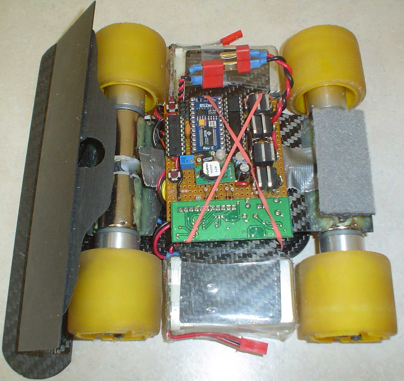
 Finally, the assembly is complete. A rubber band was added to hold the circuit board in place. Extrasensory is now ready for the next round of electronic and mechanical testing. For some reason, the photo was taken with the robot pointed to the right instead of the left. Could it be a subconscious attempt to confuse the reader? Finally, the assembly is complete. A rubber band was added to hold the circuit board in place. Extrasensory is now ready for the next round of electronic and mechanical testing. For some reason, the photo was taken with the robot pointed to the right instead of the left. Could it be a subconscious attempt to confuse the reader? |
||||
 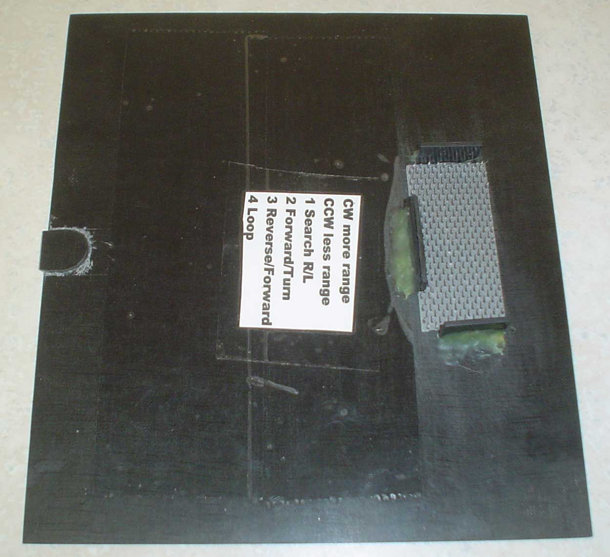 A carbon fiber graphite front plate was added to the front bumper to absorb and reflect opponents sonar and IR. It is held onto the machined aluminum front bumper with double stick carpet tape. The plate extended down to almost cover the sensors. A top plate was added to deflect an opponent's sonar and protect Extrasensory's electronics. As can be seen from the videos, Extrasensory spends a lot of time under other robots. The top plate is held on with a tab that fits in a slot in the front bumper, and industrial strength "hook and eye" material at the rear. The top plate must be tilted up at the rear to reach the pushbuttons for the start, and then pushed into place for the match. More clear packing tape was added to the top to electrically insulate the circuit board from the conductive carbon fiber. I also need a note to remind me what the start routines are. A carbon fiber graphite front plate was added to the front bumper to absorb and reflect opponents sonar and IR. It is held onto the machined aluminum front bumper with double stick carpet tape. The plate extended down to almost cover the sensors. A top plate was added to deflect an opponent's sonar and protect Extrasensory's electronics. As can be seen from the videos, Extrasensory spends a lot of time under other robots. The top plate is held on with a tab that fits in a slot in the front bumper, and industrial strength "hook and eye" material at the rear. The top plate must be tilted up at the rear to reach the pushbuttons for the start, and then pushed into place for the match. More clear packing tape was added to the top to electrically insulate the circuit board from the conductive carbon fiber. I also need a note to remind me what the start routines are. |